What are Transistors and How Do I Use Them?
Transistors are electrical components that amplify small signals into big signals. They take a small amount of power and release a large amount of power. The transistor functions like an aerosol can; small amount of force on the nozzle can release lots of energy.
Transistors are constructed using semiconductors, which only conduct electricity under the right conditions. They are typically built using three layers of silicon that are chemically treated to be slightly different. By biasing the material in the middle of the semiconductor (changing its voltage with reference to the rest of the device), the main current path of the transistor will either allow current to flow or greatly restrict the flow. Because it can control the flow of power without any moving parts (like a relay), transistors and other semiconductor components are called solid-state components.
Different Types of Transistors
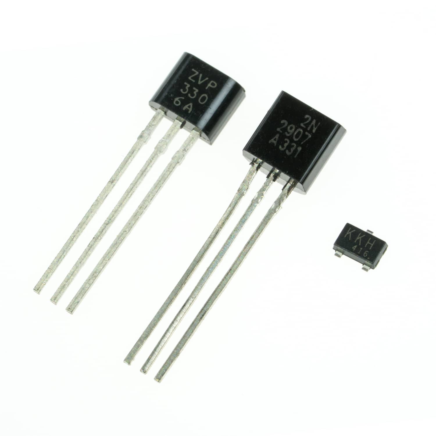
There are two main categories of transistors, BJT & MOSFET, and each of those come in two types.
BJT (Bipolar Junction Transistors)
The BJT is best described as a current amplifier. The three terminals on a BJT are called the collector, emitter, and the base. The primary current path is between the collector and the emitter. The base is used to bias the transistor to control the primary flow.
The two types of BJT are NPN and PNP. The names NPN and PNP come from the construction of a BJT. A semiconductor material such as silicon (used in most semiconducting devices) does not conduct electricity in its elemental state. To make it able to conduct electricity, elemental silicon is intentionally “doped” with other materials. These materials are either positively charged (P) or negatively charged (N). Negative dopants, such as phosphorous, have an excess of electrons that can move around. Positive dopants, like boron, have “holes” that can be filled with electrons. Now, depending on the voltage bias, electrons can move from N materials into P materials creating a conductive pathway, which allows electricity to flow.
The amount of current that is allowed to flow through the main pathway of a BJT is directly proportional to the amount of current flowing through the base of the transistor. The ratio of these two currents is the transistor’s Beta level (AKA hFE). For many BJTs, their Beta level is about 100. That means that is you allow 1mA of current to flow through the base of the transistor, the transistor will allow 100mA of current to flow through the collector and emitter.
What we haven’t yet discussed is the direction of current flow through a transistor. As you might have guessed, this is dependent on the construction of the transistor’s layers.
NPN Transistor
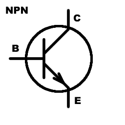
An NPN transistor is constructed with N layers on the outsides (collector and emitter) and a P layer in the middle (base). The main (large) flow of current is from the collector to the emitter. The flow of current through the base of an NPN transistor flows into the base and out of the emitter. What this means is that the voltages on the terminals must create the correct current flows. The collector must be the highest voltage on an NPN transistor. Then, current can flow from the collector to the emitter. Similarly, the voltage of the base must be higher than the voltage of the emitter when the transistor is on and lower than or equal to the emitter voltage when the transistor is off. To achieve this, an NPN transistor is usually used between the load and ground. Then, the emitter will always be equal to or lower than the voltage on the collector and emitter.
PNP Transistor
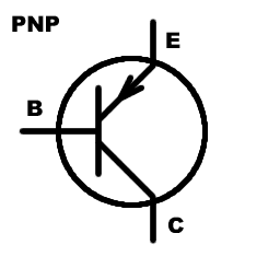
A PNP transistor is constructed with P layers on the outsides (emitter and collector) and an N layer in the middle (base). The main (large) flow of current is from the emitter to the collector. The flow of current through the base of a PNP transistor flows into the emitter and out of the base. Again, the voltages on the terminals must create the correct current flows. The emitter must be the highest voltage on a PNP transistor. Then current flows from the emitter to the collector. The voltage of the base must less than the emitter voltage when the transistor is on and greater than or equal to the emitter voltage when the transistor is off. To achieve this, a PNP transistor is usually used between the source and the load. Then, the emitter will always be equal to or greater than the voltage of the collector or base. The charge of the gate is with respect to the source or drain, depending on the type of MOSFET.
MOSFET (Metal Oxide Field-Effect Transistors)
While BJTs are current amplifiers, MOSFETs are more like voltage actuated resistors. MOSFETs also have three terminals called the drain, source, and gate. The main current path flows through the source and the drain, while the gate is charged to open or close the MOSFET. Unlike the BJTs that are built in layers, MOSFETs have a full path, or channel, of one type of semiconductor material; P or N type. Then the opposite type is placed next to the channel (e.g. an N-channel MOSFET has some P material next to the channel). These two materials are then biased to a conductive state with an electric field, rather than a flow of current. So, opening a MOSFET is like charging a capacitor. It does not require continuous current to keep it open.
Unlike the BJTs that are built in layers, MOSFETs have a full path, or channel, of one type of semiconductor material; P or N type. Then the opposite type is placed next to the channel (e.g. an N-channel MOSFET has some P material next to the channel). These two materials are then biased to a conductive state with an electric field, rather than a flow of current. So, opening a MOSFET is like charging a capacitor. It does not require continuous current to keep it open. The resistance of a MOSFET is proportional to the electric charge on the gate. With no charge, the MOSFET has an enormous resistance, which essentially makes an open circuit. When the gate is fully charged, a MOSFET can have a resistance of less than a milliohm. A gate of a typical MOSFET needs to be charged up to 1.5 – 10V to be fully open. The MOSFETs on the low end of this gate voltage range have internal circuitry to boost the gate voltage higher than the externally applied voltage. These are considered logic level MOSFETs.
Most MOSFETs today contain a built-in diode to prevent damage from electrostatic shock. This is called the body diode. The MOSFET needs to be oriented so that the body diode faces opposite the intended flow of current through the MOSFET (pointing at the higher voltage). Otherwise, current will always flow from high voltage to low voltage, though and body diode.
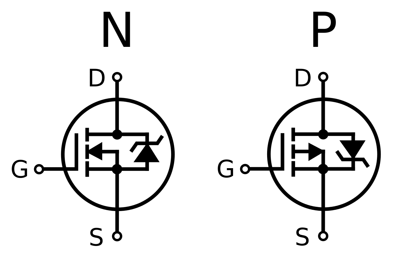
N-Channel MOSFET
An N-channel MOSFET is turned on by charging the gate to a voltage higher than the voltage of the source terminal. This generates the electric field required to draw electrons out of the N-channel and into the adjacent P material, creating a conductive path. An N-channel MOSFET is usually placed between the load and ground, so that the gate can easily be driven with a voltage higher that the source terminal. The MOSFET is turned off by pulling the gate terminal back down to ground.
P-Channel MOSFET
A P-channel MOSFET is turned on by pulling the gate voltage lower than the voltage of the source terminal. This creates and electric field that draws electrons from the adjacent N-material into the P-channel, creating a conductive path. It is turned off by pulling the gate terminal back up to (or greater than) the voltage of the drain terminal. This allows a P-channel MOSFET to be easily used between the source and the load, because the source terminal will always be the highest voltage in the circuit, allowing the gate to easily be pulled to a voltage lower than the source.
When to use a MOSFET versus BJT
Use a MOSFET when:
- The transistor must be switched using voltage, not current.
- A large current must be switched using a low current device, such as a microcontroller.
Use a BJT when:
- The transistor must be switched using current, not voltage.
- A linear region is desirable, such as an amplifier circuit.
How do I Use Transistors?
Transistors can be used in two ways: digitally or analog. When using transistors digitally, they are driven all the way open to all the way closed, like a switch. To use transistors as analog devices, they are opened partially to regulate the power running through it.
Using Transistors as Switches
Using a BJT as a Switch
Because a BJT is truly a current amplifier, it is always operating in its “linear” region of operation. In linear operation, the transistor opens proportionally to the control signal (base current). So, to use a BJT as a switch, you need enough current flowing through the base that it will easily allow all of the needed current to flow through the collector and emitter. Because a BJT is very similar to a diode, it does not resist the flow of current, it only imposes a voltage drop. Because of this, the current through the collector and emitter, and the current through the base has to be limited by a resistance. Choosing this resistance for the base is a simple matter of taking the voltage from the base to the emitter (NPN) or the collector to the base (PNP), subtracting the voltage drop of the transistor (usually about 0.6V), and dividing that voltage by the needed base current. The minimum base current needed to operate as a switch is equal to the desired emitter-collector current divided by the transistors beta level (hFE).
Using an NPN BJT as a Switch
If we needed to switch 1A of current through the emitter-collector and the transistor has a beta of 100, we need to have at least 10mA flowing through the base when the transistor is turned on.
\(\large I_{base} = \frac{I_{collector}}{hFE} = \frac{1A}{100} = 10mA\)
If this is an NPN transistor and the voltage at the base is 5V and the emitter is connected to ground, there needs to be 440Ω of resistance in series with the base.
\(\large R_{base} = \frac{V_{base-collector}}{I_{base}} = \frac{5V – 0.6V}{0.010A} = 440\Omega\)
Because a little more current will help open the transistor more, I would probably use a 330Ω resistor which would result in 13.3mA, which will allow upto 1.33A to flow through the collector and emitter.
\(\large I_{base} = \frac{V_{base-collector}}{R} = \frac{5V – 0.6V}{330\Omega} = 13.3mA\)
\(\large I_{collector} \leq I_{base} \times hFE = 13.3mA \times 100 = 1.33A\)
Using a MOSFET as a Switch
A MOSFET lends itself very well to being used as a switch because its linear operating region is very small. When a MOSFET’s gate is charged above the threshold voltage, the resistance of the MOSFET decreases dramatically, allowing current to flow easily. The resistance of the MOSFET will continue to decrease as the voltage of the gate is increased which can be done to decrease power losses in the MOSFET.
A MOSFET, unlike a BJT, does not require a resistor on the gate to limit the current. You may need to limit the inrush current with a resistor if you are charging the gate from a low current device like a microcontroller. A MOSFET does, however, require a pull-up or pull-down resistor to ensure that it turns off. If you simply disconnect a MOSFET’s gate from the control signal it will not necessarily turn off, because the gate is still charged and that charge has nowhere to go.
Using Transistors as Amplifiers
I’ve alluded to the fact that transistors do not always open and shut completely and that this can be used to restrict the flow of power. This operation is known as a transistor’s linear operation region. In this mode of operation, a transistor can be used in a circuit to amplify voltage or current. BJTs are particularly good at this, while MOSFETs are not as good because of their small and somewhat unpredictable linear region.
There are three different amplifier circuits that can be made with a BJT, corresponding to the three terminals. There are the common emitter, common collector, and common base circuits. These circuits are a very complex topic on their own, so I am not going to explore them in this article. If you would like to know more about them, please follow the links to their Wikipedia pages.