This calculator will help you design a variable frequency oscillator. The TL494 IC is a versatile PWM control circuit in a single chip. This calculator will help you calculate the oscillator frequency from a set of RC values or calculate the RC values from a set of frequencies. The oscillator is programmable over a range of 1 kHz to 300 kHz. The practical values for RT and CT range from 1 kΩ to 500 kΩ and 470 pF to 10 µF. This calculator is for a TL494 push pull circuit, see below for details on single end design.
TL494 Frequency Calculator
Insert the values of your preferred timing capacitor, resistor and potentiometer. Use TAB to calculate the frequency span. Warnings are given for results that are out of datasheet specifications.
TL494 Resistance Calculator
Insert the values of your preferred timing capacitor, lower and upper frequency. Use TAB to calculate the resistor and potentiometer values. To double check the result with nearest standard value components, use the frequency calculator above.
TL494 IC circuit and the TL494 datasheet PDF
The example circuit is from the TL494 onsemi datasheet. A TL494 replacement could be the SG3525 pulse width modulator control circuit. It does however only have a single error amplifier.
This calculator references to this TL494 test circuit and TL494 inverter circuit schematic that is from my project with a TL494 half bridge converter.

TL494 Operation Frequency
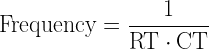
Oscillator frequency is determined by the timing components RT and CT. The external timing capacitor CT, is charged with a constant current through RT. his produces a ramping linear voltage waveform, that is discharged when it reaches 3V. However, the oscillator frequency is equal to the output frequency only for single-ended applications. For push-pull applications, the output frequency is one-half the oscillator frequency.
Single-ended applications:
Push-pull applications:

TL494 Output current
Both output transistors are configured as open collector/open emitter and each is capable of sinking or sourcing up to 200 mA. The outputs are protected against excessive power dissipation to prevent damage. They do not employ sufficient current limiting to allow them to be operated as current-source outputs.
PWM topology circuits that can be made with a TL494
The TL494 IC can be used for making a battery charger circuit, class D amplifier circuit, car amplifier power supply or a high voltage TL494 flyback driver. The TL494 current limit of the outputs is both determined by the load and the frequency at which it operates.
References
[1] Texas Instruments, Patrick Griffith: “Designing Switching Voltage Regulators With the TL494”, Application Report SLVA001B, December 2003